This message should be sent from a competent authority only, to inform about the status of different light signals at signal stations to all vessels in a certain area. The information should be displayed on an external display such as Inland ECDIS application as dynamic symbols. This message is an updated version of the “Light status message” (FI40) which cannot be updated due to the lack of a version indicator.
RIS-VTT
Initiated from shore
Parameter |
Bit |
Description |
|
| Message ID | 6 | Identifier for Message 8; always 8 | |
| Repeat Indicator | 2 | Used by the repeater to indicate how many times a message has been repeated. Default = 0; 3 = do not repeat any more |
|
| Source ID | 30 | MMSI number | |
| Spare | 2 | not used, should be set to zero | |
| Binary data | Application Identifier | 16 | DAC = 200, FI = 41 |
| Version indicator | 3 | The version number of the message default = 0, rest for future use | |
| UN country code | 12 | 2*6 Bit characters, digits 1 and 2 of the ISRS code | |
| Fairway section number | 17 | bit coded numerical value 1-99999, 0=unknown, rest not used, digits 6 to 10 of the ISRS code | |
| Object reference code - type of signal station | 3 | 0-7; 0 = default = unknown, 1 = sistat_8 (Bridge), 2 = sistat_6 (Lock), 3 = sistat_10 (Traffic), 3 = sistat_2 (Port), rest reserved for future use not used, digits 13 and 14 of the ISRS code | |
| Object reference code - number of signal station | 4 | 0-16; 0-9 = number of signal station, 10 = default = unknown, rest not used, digit 15 of the ISRS code | |
| Fairway hectometre | 17 | bit coded numerical value 1-99999, 0=unknown, rest not used, digits 16 to 20 of the ISRS code | |
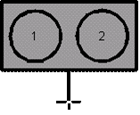
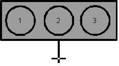
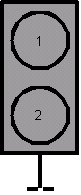
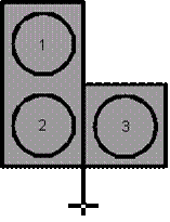
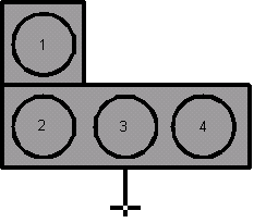
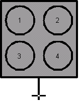
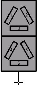
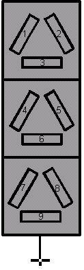
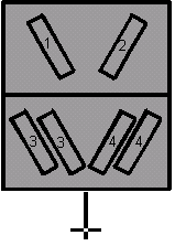
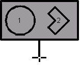
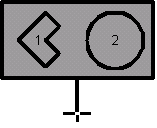
| Signal form | 4 | 0-15, 0 = unknown = default, 1-14 signal form according to Figure 3‑1 | |
| Orientation of signal | 9 | 0-511, 0 – 359 = orientation in degrees, 511 = not available = default, rest not used | |
| Direction of impact | 3 | 1 = upstream, 2 = downstream, 3 = to the left bank, 4 = to the right bank, 0 = unknown = default, rest not used | |
| Light Status | 30 | Status (1 to 7) of up to 9 lights per signal according to Figure 3‑1, 0 = default = unknown, 8-9 not used, 000000000 = default, 777777777 maximum, rest not used |
|
| Spare | 10 | not used. Should be set to zero | |
| Total | 168 | occupies 1 slot |
Reference tables:
The examples show a grey background in a square of a fixed size of about 3 mm x 3 mm at all display scales with a “post” like it is used for the present static signal in the presentation library. The white point in the centre of the post indicates the position and the post itself allows the user to read the direction of impact. (At a lock, for example, there are often signals for vessels leaving the lock chamber and vessels entering the lock chamber on the inner and the outer side of the door construction) However, the manufacturer of the display software can design the shape of the symbol and the background colour.
The status of a signal can be “No light”, “white”, “yellow”, “green”, “red”, “white flashing” and “yellow flashing” according to CEVNI.
 |
 |
 |
 |
| 1 | 2 | 3 | 4 |
 |
 |
 |
| 5 | 6 | 7 |
|
 |
 |
 |
| 8 | 9 | 10 | 11 |
 |
 |
 |
| 12 | 13 | 14 |
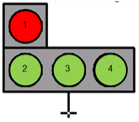
For each of these signals there are a lot of possible combinations of lights. It is required to use
A number to indicate the kind of signal and
A number for each light on a signal to indicate its status
 |
 |
 |
 |
 |
 |
 |
| 1 | 2 | 3 | 4 | 5 | 6 | 7 |
 |